What Is a Machine Press Machine and What Types Are There?

A machine press machine converts controlled force into forming, cutting, stamping, or assembling work. Its frame, drive, tooling, and control system determine how that force reaches the material. In a fabrication shop, the difference is tangible: a flywheel press cycles differently from a hydraulic press, while a guarded, well-adjusted work area supports safer, more consistent operation. The term covers several machine families, not one universal design.

Choosing a press starts with the job. Part geometry, material thickness, required tonnage, stroke length, production volume, and changeover needs all matter. The U.S. Bureau of Labor Statistics’ 2023 Survey of Occupational Injuries and Illnesses provides workplace injury and illness data by industry. It is useful context, but it does not isolate every press type or prove that one design is inherently safer. Buyers should pair such data with equipment specifications, guarding details, and hands-on risk assessments. Small details count.

Taiichi Ohno, a manufacturing-system expert, wrote, “Where there is no standard, there can be no improvement.” That principle applies to press setup, inspection, and operator training—not just production targets. This guide explains what a machine press machine does and compares mechanical, hydraulic, pneumatic, and servo-driven types. Their strengths differ in speed, force control, precision, and maintenance. There is no perfect press for every shop; matching the machine to the actual work takes careful review, and sometimes a second look.
What Is a Machine Press Machine and What Types Are There?

What Is a Machine Press?

A machine press is a powered machine that applies force to shape, cut, or compress material. A workpiece rests on a bed or inside a die, while a moving ram travels through a set stroke. The tool’s shape and the press force determine the operation. A press may punch holes in sheet metal, bend a bracket, or compress powder into a compact form. Some machines use a flywheel and crank; others rely on hydraulic fluid or servo-driven motion. The term sounds simple. The setup is not.

Press capacity, stroke length, and operating speed matter because they affect the result and the risks around the work area. A press rated for a certain tonnage does not make every die or material suitable for it. Operators also need to consider how stock is positioned and how hands stay clear of moving parts. The U.S. Bureau of Labor Statistics reported about 2.6 million nonfatal workplace injury and illness cases in private industry in 2023. That figure covers many industries and is not a count of press-related incidents, but it underscores why machine setup and safe work practices deserve attention. A detail can be missed. The distinction between a machine’s rated capacity and a safe working setup deserves a second look.

How a Machine Press Applies Force

A machine press applies force by driving a ram, or slide, toward a workpiece held on a bed or within a die. The force path runs from the drive system through the frame and tooling, then into the material. Different presses create this movement in different ways. In a mechanical press, a motor turns a flywheel, while a crank or linkage converts rotation into a ram stroke. Hydraulic presses use fluid pressure acting on a piston, allowing force to build steadily through much of the stroke. Pneumatic presses use compressed air and often suit lighter, faster operations. The feel differs.

At the tool, the ram closes and the tooling contacts the part. The applied force may shape, cut, or join the material. But a machine’s rated tonnage does not tell the whole story. Stroke position, tooling geometry, material thickness, and frame stiffness all affect the load at the contact point. A press may not deliver force uniformly across a wide die. Alignment matters. A slight offset can concentrate load on one edge, leading to uneven results or faster tool wear. It is easy to overlook. Operators check setup, material placement, and guarding before cycling, though small variations can still surprise. Pressure gauges and load monitoring help, but they do not replace careful setup and inspection.

Key Components of a Machine Press

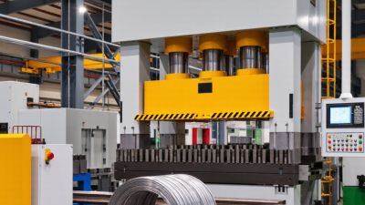
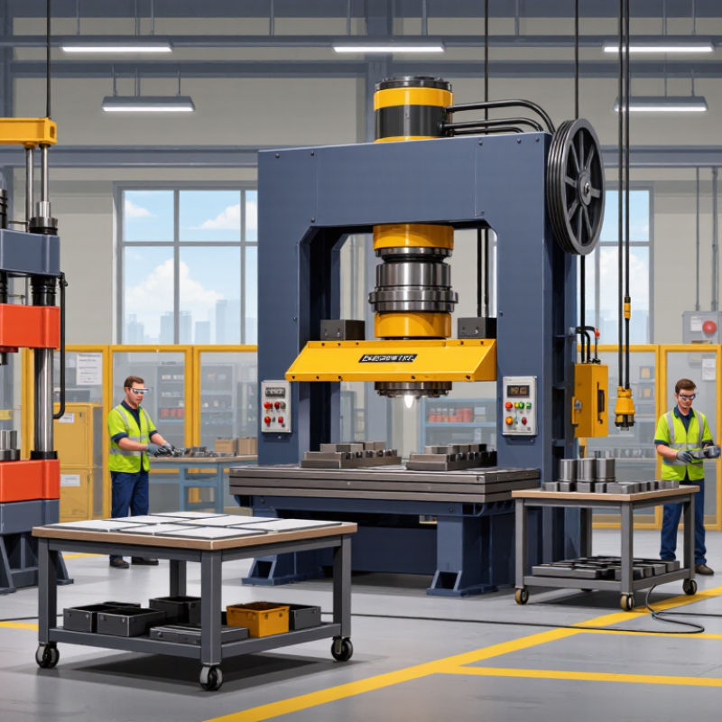
A machine press turns force into controlled movement, but its frame carries the load. The bed supports the die, while the ram, or slide, moves the upper tool toward it. On a mechanical press, a motor, flywheel, crank, and connecting rod drive the slide. A hydraulic press uses cylinders and fluid pressure instead. Different drive systems change how force builds through the stroke. That distinction matters.

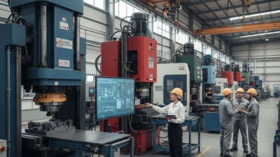
The clutch and brake control motion on many mechanical presses; hydraulic systems use valves to direct fluid. Controls set the cycle, while guards and presence-sensing devices help keep hands away from danger zones. Dies shape or cut the material, so their alignment with the bed and ram is critical. Small parts matter. The U.S. Bureau of Labor Statistics reported 2.6 million recordable injury and illness cases in private industry in 2023; this figure covers all industries, not presses alone. It is a useful reminder that machine design and safe work practices belong together. In practice, operators should check for loose fasteners, unusual vibration, and uneven die contact. A press may look sound and still need inspection.

What Is a Machine Press Machine and What Types Are There? - Key Components of a Machine Press

A machine press is a machine tool that applies force to shape, cut, form, or assemble material, commonly sheet metal. Its frame supports the working load, while a drive system moves a ram or slide and tooling performs the operation.

Type or Component How It Works Key Components Typical Characteristics or Uses
Mechanical press A motor drives a flywheel and mechanical linkage, such as a crank or eccentric, to move the slide. Motor, flywheel, clutch and brake, crankshaft or eccentric, connecting rod, slide, frame, and die. Provides rapid, repeatable strokes. Commonly used for stamping, blanking, punching, and forming operations suited to its capacity and stroke.
Hydraulic press Pressurized hydraulic fluid moves one or more cylinders to apply force to the ram. Hydraulic pump, reservoir, fluid lines, valves, cylinder, ram, frame, and control system. Can apply force throughout the stroke and allows adjustable pressure and speed. Often used for deep drawing, forming, and pressing jobs that require controlled force.
Pneumatic press Compressed air drives a pneumatic cylinder that moves the ram or tooling. Air supply, filter-regulator, directional control valve, cylinder, ram, frame, and controls. Often suited to lighter-duty, short-stroke tasks such as assembly, marking, and small-scale punching. Available force depends on air pressure and cylinder area.
Servo-electric press An electric servo motor drives the slide through a mechanical transmission, with motion managed by electronic controls. Servo motor, drive and controller, transmission, slide, position or force sensors, frame, and tooling. Allows programmable slide motion and precise control of position and speed. Used where repeatability and flexible motion profiles are important.
Frame and bed The load-bearing structure supports the drive system and resists forces generated during pressing. Frame, uprights or side frames, crown, bed, and tie rods or other structural members where fitted. Frame design affects rigidity, access to the work area, and the size of parts and dies that can be accommodated.
Slide, ram, and guides The slide or ram carries the upper tooling and moves toward and away from the workpiece; guides help control its movement. Slide or ram, guideways, connecting mechanism or cylinder connection, and adjustment features where fitted. Alignment and controlled movement help maintain consistent contact between the upper and lower tooling.
Bolster, die, and tooling The bolster supports the lower tooling, while the die set shapes, cuts, or forms the material during the stroke. Bolster plate, upper and lower die sections, punches, guides, and workholding or locating features as required. Tooling is selected for the operation and material. Examples include blanking, bending, punching, and forming dies.
Controls and safety devices Controls start, stop, and manage press operation; safety devices help protect operators from hazards. Operator controls, emergency stop, guards, interlocks, and presence-sensing devices where appropriate. Safeguarding must be selected and configured for the specific press, tooling, and task. Operators should follow applicable safety procedures and regulations.

Common Types of Machine Presses

Common Types of Machine Presses

A mechanical press uses a motor and flywheel to drive a ram through a crank or similar linkage. It can cycle quickly, making it useful for repeated stamping and blanking work. The ram’s force changes during its stroke, so tooling and material thickness matter. Listen for unusual vibration. It can signal wear, but it is not a diagnosis.

A hydraulic press uses pressurized fluid to move its ram. It can apply substantial force at low speeds and hold pressure during forming, such as bending a thick plate. Operators can often adjust the stroke and pressure, though cycle times may be slower than on many mechanical presses. Leaks, fluid temperature, and seal condition affect performance. Small details matter.

Pneumatic presses use compressed air and are often suited to lighter, quicker tasks, such as assembling small components.

Servo presses use an electric motor to control ram movement, allowing programmed speed and position changes.

Some presses also use toggle linkages, which increase force near the end of a stroke. These labels can overlap: a press may combine a drive type with a particular linkage. Choosing between them is not always obvious; production rate, material, required force, and process control all deserve attention.

Typical Uses and Selection Factors

Machine presses apply controlled force to cut, bend, shape, or assemble materials. A small bench press may seat bushings or flatten thin sheet. Larger presses stamp brackets, punch holes, or form appliance panels. Mechanical presses suit fast, repeatable strokes. Hydraulic presses provide adjustable force through a longer stroke, making them useful for deep forming and pressing assemblies. Pneumatic presses often handle lighter, quick tasks. Servo-driven systems offer programmable motion, though their added controls may not suit every shop. The right press depends on the work, not the label.

Start with material thickness, strength, and the operation’s force requirements. A press rated for a certain tonnage may not provide that force at every point in its stroke. Check bed area, stroke length, shut height, and room for the die. Then compare cycle rate and required accuracy. Consider how operators load parts, change tooling, and remove scrap. Guarding and accessible maintenance points matter in daily use. Ask for a trial with representative stock, if possible. Real parts reveal issues drawings miss. Measuring every clearance can feel excessive, but a tight setup can become an expensive mistake.