What Are the Top Advanced Metal Fabrication Machines?

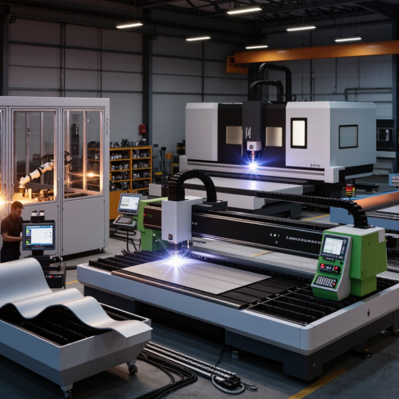
Modern metal fabrication shops face a crowded choice of machines, each promising speed, accuracy, or flexibility. This introduction to the top advanced metal fabrication machines looks beyond impressive specifications. It considers what each system can do on the shop floor, where it fits, and what operators must manage. The phrase advanced metal fabrication and machine work covers a wide field, from automated cutting to precision forming and joining. No single machine suits every job.

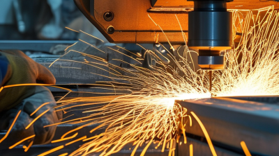
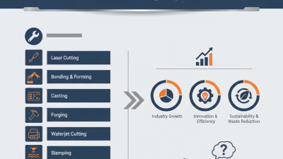
Laser cutters can produce clean, detailed profiles. CNC press brakes form repeatable bends, while waterjet systems handle heat-sensitive materials. Robotic welding cells can improve consistency, but they still require careful setup and inspection. CNC machining centers remove material with controlled precision. Plasma cutters remain useful for many thicker plate applications. Some differences are easy to miss. A fast cycle time may matter less than setup time, maintenance needs, or the skill required to keep parts consistent.

Quality-management pioneer W. Edwards Deming offered a useful caution: “It is not necessary to change. Survival is not mandatory.” His words are not a machine-buying rule, but they encourage thoughtful improvement rather than change for its own sake. The sections that follow compare leading machine types, their strengths, and their practical limits. A machine’s real value depends on the material mix, part complexity, production volume, and available expertise. Specifications help, but they do not tell the whole story. The best choice may be less obvious than it first appears.
What Are the Top Advanced Metal Fabrication Machines?

Core Functions and Selection Criteria for Advanced Metal Fabrication Machines

Advanced metal fabrication machines perform distinct tasks, so selection should start with the part, not the machine category. Laser cutters handle detailed profiles in sheet metal, while press brakes form accurate bends. Waterjet systems can cut heat-sensitive materials; robotic welding cells support repeatable joints across longer production runs. Each tool has limits. A fast cutting head cannot compensate for poor material handling or inaccurate drawings.

Match capacity to real jobs. Check material type and thickness, required tolerances, daily volume, and the size of the largest workpiece. Then assess setup time, floor space, electrical supply, fume extraction, software compatibility, and operator training. These details shape output as much as rated speed. Fit matters. Ask how quickly consumables can be replaced and whether maintenance access is practical. A machine that stops often may erase its apparent productivity advantage.

Run representative parts before committing, including awkward shapes and frequently repeated components. Inspect edge quality, bend consistency, cycle time, and scrap levels. A polished demonstration may not reflect a crowded shop floor. Be cautious with capacity claims that omit material grade or operating conditions. There is no perfect selection; production needs change, and estimates can be wrong. Leave room for future tooling or workload changes, but avoid paying for capacity that sits idle.

Fiber Laser Cutters for High-Precision Sheet and Plate Processing

Fiber laser cutters have become central to high-precision sheet and plate processing. Their concentrated beam can produce narrow cuts and small features, while automated motion helps maintain repeatability across batches. Grand View Research estimated the global laser cutting machine market at USD 6.14 billion in 2023, with projected growth of 7.7% annually from 2024 to 2030. That market estimate signals investment, not a guarantee that every shop will gain the same productivity.

On the shop floor, results depend on more than laser power. A stable cutting bed, clean optics, suitable assist gas, and well-tuned parameters all affect edge quality. For example, a thin stainless-steel sheet may need different settings from a thick carbon-steel plate. Check the cut edge for dross and heat discoloration, then review kerf width and dimensional tolerance against the drawing. Small details matter. A rushed setup can waste material, even on a capable machine.

Tips: Run a test cut on the same material grade and thickness before production. Record power, speed, focus position, and assist-gas settings. Recheck them after changing materials or nozzles. A perfect-looking edge is useful, but it does not replace measuring the finished part.

CNC Press Brakes for Automated Metal Forming

CNC press brakes make automated metal forming more repeatable by controlling ram movement, bend angle, and backgauge position. An operator can load a sheet, select a verified program, and form a sequence of bends with consistent spacing. On a typical job, the machine may handle a 1.5-millimeter steel panel with several flanges. Correct tooling and a stable setup matter as much as the program.

Automation reduces measuring and repositioning, but it does not remove the need for judgment. Material thickness, grain direction, and springback can shift the final angle. A part that looks right at the first bend may still drift later. Measure a test piece with an angle gauge, then adjust the program before running a full batch. Small setup errors can multiply.

Tips: Keep punch and die surfaces clean. Confirm the sheet thickness before loading. Check the first finished part, especially near tight corners. Record useful corrections for repeat jobs. A note about an unusual material batch can save time later, though records are easy to overlook during a busy shift.

Robotic Welding Systems for Consistent Joint Fabrication

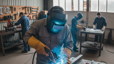
Robotic welding systems help fabrication shops produce repeatable joints across production runs. A robot follows a programmed torch path while controlling travel speed and torch angle. Depending on the setup, it can also maintain consistent wire-feed settings. The practical gain is consistency, not magic. Small variations in part fit can still cause gaps or uneven welds. A rigid fixture and accurate part positioning matter just as much.

Technicians typically test the program on sample pieces, then inspect bead shape and joint penetration before production begins. Sensors can track seams when parts shift slightly, but they cannot correct every fit-up problem. Fit-up still matters. Operators also need to check torch condition, cable wear, and calibration at regular intervals. These checks take time, yet skipping them can turn a stable process into a costly rework cycle.

A useful system should match the joint type, material thickness, and production volume. For example, a long, straight seam may suit a fixed robotic cell, while frequent part changes may require more flexible fixturing. It is tempting to automate every weld. That is not always wise. Some short or awkward joints may be faster to complete manually, especially when programming and setup exceed the welding time. The best results come from measuring the whole task, not just the robot’s speed.

What Are the Top Advanced Metal Fabrication Machines? - Robotic Welding Systems for Consistent Joint Fabrication

A practical comparison of common advanced fabrication machines. Actual capacity and results depend on machine configuration, material, tooling, programming, and operator setup.

Machine Type Primary Function How It Supports Consistency Typical Applications Key Consideration
Robotic welding system Automates repeated welding paths, commonly using processes such as gas metal arc welding. Programmed torch motion and controlled process settings help repeat weld position and travel across similar parts. Sensors or seam-tracking equipment can help compensate for joint variation. Production runs with repeatable joints, including frames, enclosures, and structural assemblies. Reliable results still require suitable joint fit-up, fixturing, weld procedure, and operator oversight.
CNC fiber laser cutting machine Cuts sheet or plate by focusing a laser beam along a programmed path. CNC motion and stored cutting parameters support repeatable profiles and hole locations when material and setup are controlled. Flat components, intricate contours, and nested sheet-metal parts. Material type, thickness, assist gas, and surface condition affect cut quality and speed.
CNC press brake Forms sheet metal by pressing it between a punch and die. Programmable backgauges and ram control help repeat bend positions and angles; angle measurement systems can correct for springback. Brackets, panels, channels, cabinets, and other formed components. Tool selection, material grain direction, thickness, and springback influence the finished bend.
CNC waterjet cutting machine Cuts material with a high-pressure water stream, often mixed with abrasive for metals. Programmed tool paths produce repeatable shapes, and the process introduces little heat compared with thermal cutting methods. Thick plate, heat-sensitive materials, and parts requiring minimal heat-affected edges. Cut speed and edge quality depend on material, thickness, abrasive flow, and nozzle condition.
CNC plasma cutting table Uses an electrically conductive plasma arc to cut conductive metals. CNC-controlled motion and torch-height control help maintain the programmed profile and torch distance from the plate. Cutting steel and other conductive plate, particularly for larger or heavier parts. Kerf, dross, and heat input vary with plate thickness, consumable condition, and cutting settings.
CNC turret punch press Punches holes and shapes in sheet metal using indexed tooling. CNC positioning and repeatable tool indexing support consistent hole patterns and formed features. Perforated panels, electrical enclosures, and sheets with repeated holes or simple forms. Tool availability, punch clearance, and sheet thickness affect feature quality and production efficiency.
CNC machining center Mills, drills, or taps metal components using programmed cutting tools. CNC programs, workholding, and tool offsets help reproduce dimensions and features across batches. Machined plates, fixtures, precision brackets, and parts requiring milled features. Tool wear, workholding, and thermal effects can influence dimensional accuracy.

Metal Additive Manufacturing Machines for Complex Components

Metal additive manufacturing machines build complex components layer by layer from digital designs. They can produce internal channels, lattice structures, and curved passages that are difficult to machine from solid stock. This makes them useful for prototypes and parts where weight or geometry matters. The machine’s laser or electron beam melts selected regions of metal powder, while controlled build conditions help limit defects. Small details matter: powder consistency, support placement, and thermal management can all affect the finished part. Not every intricate shape prints reliably, though.

Choosing a system means looking beyond its advertised build volume. Check the materials it can process, the machine’s monitoring tools, and the post-processing equipment required. Printed components may need heat treatment, support removal, and precision machining before inspection. These steps add time and cost. A practical evaluation uses a representative part, not just a demonstration sample. Measure surface finish, dimensional accuracy, and repeatability across multiple builds. Results can be uneven at first; that is a reason to refine the workflow, not ignore the data.

Tips: Keep a small test coupon in early builds. It can reveal changes in density or surface quality before they affect a critical component. Record powder handling, build settings, and finishing steps. Clear records make troubleshooting easier, though they cannot prevent every failed build.

Metal Additive Manufacturing: Representative Layer Heights

Illustrative layer-height examples for common metal additive manufacturing processes. Actual settings vary with machine, material, and process parameters; the logarithmic scale makes differences across the processes easier to compare.