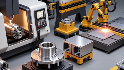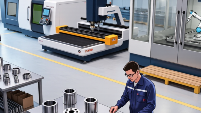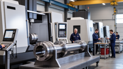
China has become a significant sourcing destination for custom fabrication and machine solutions. Its manufacturers serve industries such as automation, energy, construction, medical equipment, and transportation. Capabilities often include CNC machining, laser cutting, sheet-metal forming, welding, casting, surface finishing, and complete assembly.
A reliable supplier should offer more than polished photographs. Buyers need verified material certificates, controlled drawings, inspection records, and clear production communication. Dimensional tolerances, weld penetration, surface roughness, and packaging details can decide whether a component performs safely. Small details matter. A two-millimeter error may stop an entire assembly line.
Elon Musk once said, “The machine that makes the machine is more important than the machine itself.” This observation reflects the importance of process capability, not only the final product. In custom fabrication and machine projects, experienced engineers review manufacturability before production begins. They identify weak joints, unnecessary machining steps, difficult tolerances, and avoidable costs. Strong manufacturers also explain limitations honestly. That builds trust.
No supplier is flawless. Even a capable factory may misunderstand a drawing or miss a finishing requirement. Practical buyers reduce this risk through sample approval, staged inspections, and documented change control. Factory visits and video inspections can provide useful evidence, although they cannot replace technical testing. The best partnership combines engineering experience, transparent quality systems, and consistent after-sales support. This guide examines how to evaluate China-based manufacturers, compare technical capabilities, and select a dependable partner for demanding fabrication projects.
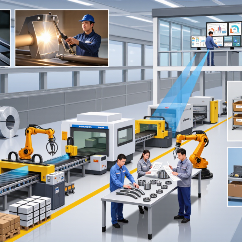
China’s custom fabrication and machine manufacturing covers the conversion of customer requirements into physical parts, assemblies, and working equipment. It may include engineering design, material selection, CNC machining, sheet metal work, welding, casting, surface treatment, and final assembly. The definition sounds neat, but reality is less tidy. A drawing can still hide tolerance conflicts, weak joints, or difficult production steps.
The scope usually begins with concept review and prototype development. It can continue through process planning, tooling, batch production, inspection, packaging, and technical documentation. Experienced manufacturers examine critical dimensions, material certificates, weld quality, surface finish, and machine safety. They also clarify quantities, delivery conditions, testing methods, and change-control procedures before production starts. Small details matter here.
Reliable cooperation depends on evidence, not attractive claims. Buyers should request sample inspection records, capability information, process photographs, and clear responses to technical questions. A supplier may offer advanced equipment, yet equipment alone does not guarantee stable results. Operator skill, maintenance, measurement systems, and process discipline are equally important. Even a careful inspection plan can miss a practical assembly problem. That deserves honest review.
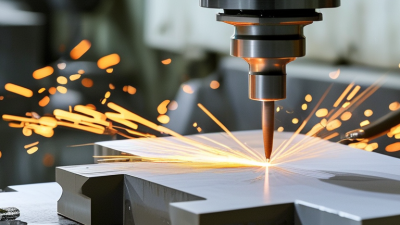
Custom fabrication succeeds when each process matches the part’s real demands. Our workshop combines 3–5-axis CNC machining, laser cutting, and welding for accurate assemblies. Five-axis machining reaches angled surfaces with fewer setups. Three-axis machining remains practical for simpler profiles and controlled budgets. Laser cutting produces clean outlines quickly, especially on sheet metal. Welding then joins prepared parts into strong, usable structures.
Every project begins with drawings, material checks, and practical process planning. We review wall thickness, tolerances, hole locations, and possible distortion. A machined aluminum plate may need careful clamping to prevent movement. Welded steel frames require heat control and inspection after cooling. We measure critical dimensions with calibrated tools. Surface burrs are removed by hand, not ignored.
No process is perfect. We have seen small drawing gaps create expensive rework, so clear communication matters.
Tips: Share 3D files, 2D drawings, material grades, and tolerance priorities. Mark appearance-critical surfaces. Ask for a sample inspection report before full production. Keep weld access visible in the design. Small changes help. Also, review the first article honestly; one tolerance may still need adjustment.
Achieving ±0.01 mm CNC tolerance requires more than a precise machine. It demands stable fixturing, calibrated inspection tools, controlled cutting conditions, and experienced operators. A 2024 market assessment estimated the global CNC machine market at approximately USD 83.99 billion in 2023, reflecting strong demand for dependable precision manufacturing. Yet machine capacity alone does not guarantee repeatable results.
DFM optimization starts before cutting begins. Engineers review wall thickness, hole depth, corner radii, datum locations, and material behavior. Small changes can reduce tool deflection, shorten cycle time, and improve inspection access. For example, replacing an unnecessarily deep pocket with a manufacturable radius may prevent vibration and protect the ±0.01 mm requirement. The 2023 State of Design and Make report identified cost control and production efficiency as major manufacturing priorities, making early design review commercially important.
Details matter most. A shop should confirm tolerance zones, surface-finish expectations, and critical dimensions before production. Coordinate measuring machines then verify parts against the approved drawing, not assumptions. Our own process reviews sometimes reveal an uncomfortable truth: a drawing may request ±0.01 mm where ±0.03 mm performs equally well. That precision can increase cost without improving function. Good engineering challenges such requirements carefully. It does not simply promise tighter numbers. Reliability comes from documented inspections, traceable materials, controlled revisions, and honest communication when a design needs refinement.
| Engineering Dimension | Typical Capability or Data | Application and Notes |
|---|---|---|
| CNC Milling Tolerance | Up to ±0.01 mm for selected features | Requires suitable material, tooling, machine condition, temperature control, and inspection planning. |
| General CNC Machining Tolerance | Commonly ±0.02 to ±0.05 mm | Suitable for most housings, brackets, fixtures, and functional prototype components. |
| CNC Turning Tolerance | Typically ±0.01 to ±0.03 mm on controlled diameters | Suitable for shafts, pins, bushings, threaded parts, and rotational components. |
| Dimensional Inspection | Calipers, micrometers, height gauges, gauges, and CMM inspection | Inspection equipment should be selected according to feature size, tolerance, geometry, and measurement uncertainty. |
| Surface Roughness | Machined surfaces commonly Ra 1.6–3.2 µm; finer finishes may be specified | Actual results depend on tool geometry, feed rate, cutting conditions, material, and finishing operations. |
| Supported Metals | Aluminum alloys, stainless steel, carbon steel, brass, copper, and titanium | Material grade, heat treatment, hardness, and certification requirements should be defined before production. |
| Supported Plastics | ABS, POM, nylon, PTFE, PEEK, PC, and acrylic | Plastic parts require consideration of shrinkage, thermal expansion, moisture absorption, and deformation. |
| DFM Review | Geometry, datum structure, wall thickness, radii, holes, threads, and tool access | Design-for-manufacturing review helps reduce unnecessary machining, setup changes, scrap, and production risk. |
| Minimum Internal Corner Radius | Preferably greater than half the cutting-tool diameter | Larger internal radii generally improve tool life, cutting stability, cycle time, and cost efficiency. |
| Thin-Wall Design | Wall thickness should be selected according to material, size, depth, and fixturing | Very thin walls may vibrate, warp, or deflect during machining and may require process-specific support. |
| Threads and Holes | Metric and inch threads; drilled, reamed, counterbored, and countersunk features | Thread specification, fit class, depth, and inspection method should be included in the technical drawing. |
| Fabrication Processes | CNC milling, CNC turning, sheet-metal fabrication, laser cutting, bending, and welding | Process selection depends on geometry, material, quantity, tolerance, appearance, and total manufacturing cost. |
| Surface Treatments | Anodizing, powder coating, electroplating, passivation, black oxide, brushing, and polishing | Finish selection should account for corrosion resistance, wear, electrical performance, color, and dimensional impact. |
| Production Volume | Prototype, low-volume, and repeat production | CNC machining is well suited to complex parts and flexible quantities without dedicated hard tooling. |
| Technical File Formats | STEP, IGES, Parasolid, DXF, DWG, and PDF drawings | 3D models define geometry; 2D drawings should define tolerances, datums, materials, finishes, and inspection requirements. |
Quality Standards: ISO 9001:2015, IATF 16949, and 100% Inspection
Custom fabrication demands more than accurate drawings and modern equipment. Our quality system follows ISO 9001:2015 for controlled processes, documented decisions, and continual improvement. For automotive-related components, IATF 16949 adds stronger risk management, traceability, and process discipline. Each project begins with drawing review, material verification, and clear inspection criteria. Operators check dimensions during production, not only after machining ends.
Every finished part receives 100% inspection according to the approved control plan. Calibrated gauges verify critical dimensions, surface conditions, and assembly features. Inspection records connect each component to its batch, operator, and measurement data. When a result falls outside tolerance, the part is isolated for review. We investigate the cause instead of hiding the defect. This approach is practical, though no manufacturing system is perfect. Human judgment can still miss a detail. Regular training and process audits help reduce that risk.
Tips: Share complete drawings, tolerances, material grades, and surface requirements before production. Ask for inspection reports with measurable data. Confirm how nonconforming parts are controlled. A useful quality conversation often prevents expensive rework later. Feedback also helps us improve, even when it exposes a weakness in our process.
China Top Custom Fabrication and Machine Manufacturer
Materials and compliance determine whether a fabricated part performs safely in production. ASTM standards commonly define material grades, dimensions, and test methods. EN standards support European technical consistency across machinery and components. CE marking applies when the finished product falls under applicable European Union legislation. RoHS restricts specific hazardous substances in electrical and electronic equipment. These requirements are related, but they are not interchangeable.
The World Steel Association reported approximately 1.89 billion tonnes of crude steel production worldwide in 2023. This scale makes material traceability essential, especially for custom brackets, frames, shafts, and enclosures. In practical work, we verify the grade, heat number, inspection certificate, and surface treatment records. A drawing may look compliant, yet an incorrect coating can still create a failure. That uncomfortable gap deserves review. RoHS testing may require laboratory evidence, while CE conformity often requires risk assessment and technical documentation. Material selection should begin before machining, not after inspection.
Tips: Request the standard edition, acceptance limits, and inspection method before production. Keep certificates linked to each batch. Check whether CE applies to the complete machine, an assembly, or neither. For uncertain applications, obtain an independent compliance review. Small documentation errors can delay a container, even when the parts are dimensionally correct.
This chart shows the maximum concentration limits for the ten restricted substances covered by RoHS Directive 2011/65/EU, measured by weight in homogeneous materials. Most substances are limited to 0.1%, while cadmium is limited to 0.01%.
ASTM and EN requirements are selected according to the material, product type, and application. CE marking confirms conformity with the applicable European Union legislation; it is not a standalone material standard.